CMST LAB 9 Routing & Routing Protocols

OBJECTIVE: Become familiar with routing and routing protocols and learn how to troubleshoot a broken network connection.

EQUIPMENT LIST: Myself, a router, a switch,  PCs, Network cables, and Hyperterminal

NOTES AND OBSERVATIONS:

Configure the network as shown Project 1  Configure RIP. Then trouble shoot  as shown in Project 2 . Then contact the instructor so that he/she can ‘break’ something in your network. Once the instructor has called you back into the room, troubleshoot then fix your network.


.

Diagrams, flowcharts, and figures


TROUBLESHOOTING STRATEGY:

Step One: Check connectivity with a ping – Did not work

Step Two: Check cables connections – All checked out ok

Step Three: Check Gateway and IP addresses – They were incorrect; changed on host PC

Step Four: Check routing protocols – They had not been changed

Step Five: Check switch for power – No power to switch; reset ground fault in outlet; Network functioned again.


QUESTIONS:


1. What method did we use to check connectivity?

  •  Pings and the tracert command allowed us to test the connectivity of our network.


CONCLUSION:

  • We learned a great deal about routing protocol.  We also learned that it is possible to break a network in some unusual ways, and sometimes it pays to think outside the box and check things( like checking to see if someone cut the cord end off) that wouldn’t normally be a problem in order to fix them.
CMST LAB 9 Routing & Routing Protocols

CMST 8 Video Making

OBJECTIVE:  

  • To become familiar with tools used to download videos from Youtube and perform  basic video editing.

EQUIPMENT LIST:  

  • PC, Sony Vegas,Jamendo,

NOTES AND OBSERVATIONS:

  • None to speak of, but I did end up with the following video…

REFERENCES:

  • Mr. Genereux, Lab Handout

QUESTIONS:


CONCLUSION:

  • I had a really good time with project and look forward to doing the semester project video.
CMST 8 Video Making

CMST Lab 7 Subnetting

OBJECTIVE: The objective of this was to design and build a working network  with subnets.

EQUIPMENT LIST: PC, some cables, a switch, and a router.

IMG_0883

IMG_0884

NOTES AND OBSERVATIONS:

This lab  required the cooperation of multiple groups of people, and sometimes the router did not want to cooperate. Ended up having to replace it.

First, we drew a diagram of our proposed network, partitioning the rows in the lab into groups.  The diagram look like this:

IMG_0887

IMG_0888

IMG_0889

It was a bit messy, but it worked, and it allowed us to figure out who was on which subnet and what everyone’s respective IP addresses would be.  Each PC that was used in the network was assigned a subnet and address based upon the number of required connections. After getting our group’s computers plugged into the switch and router, we had to configure our router to function on the network within the assigned subnet.

CONCLUSION: This lab allowed us to demonstrate what we knew about subnetting, and it put it all together. It was quite effective although challenging at times.


CMST Lab 7 Subnetting

CMST Lab 6 Sniffing

OBJECTIVE: The objective of this lab was to learn about packet sniffing with the use of WireShark .

EQUIPMENT LIST:  PC, Wireshark, and some random websites.

REFERENCES: Alec Cork

QUESTIONS:

1. Locate sequence numbers used by a TCP segment.  What is the purpose of these numbers?

  •  The sequence numbers give order to the packets. So they be reassembled in the correct order by the receiving computer.

2. Find the FTP protocol frames that show where your username and password were supplied.  What do you notice about these frames?

  •  Ethernet 1 encapsulation – 68 bytes

3. What can you say about the FTP protocol after viewing these frames?

  •  The FTP isn’t very secure at all.

4. Can you locate the frames that use the “GET” and “PUT” commands used to download & upload files?  Describe what you have learned about the process of an FTP transfer by viewing these packets.

  • The FTP is not secure at all.

5. Find a frame containing a DNS query.  What protocols are encapsulated in this frame?  Which of these protocols is a transport layer protocol?

  •  Ethernet II, IPv4, User Datagram Protocol, DNS; Transport layer —> IPv4

6. Find the frame containing ICMP information.  What protocols are encapsulated in this frame?  Which layer does ICMP reside in?  What do the ICMP initials mean?

  •  2 Protocols; Layer 3 – Network

7. Find frames containing HTTP information.  Approximately how many frames did it take to download the page?

  •  74

8. Open the first frame carrying a HTTP GET request packet.  What protocol headers do you see?

  • IP of the source; IP of the destination

9. Within the HTTP header, find and record User Agent Information.  Which layer does each of the protocols belong to?

  •  Mozilla 5.0; Application layer

10. Open the first HTTP Response frame.  Find the type of web server being accessed in the frame’s header.

  •  Google Web Server

11. Find a pair of frames that show an ARP request and an ARP response.  Explain these frames and what they are doing.

  •  They are identifying the sender and target MAC and IP addresses.

12. What is the purpose of TCP sequence numbers?

  • They order the packets sending.

13. What is the purpose of the IP source & destination addresses?

  •  They identify who is sending and receiving.

14. What is the purpose of a DNS?

  •  It turns an IP address into a web domain.

15. What is DHCP?

  •  It automatically configures IP addresses.

16. What is the relationship between the OSI model and the TCP/IP model?

  •  They have very  similar architecture.

17. What evidence of layered network design did you discover when examining the captured data?  How does Wireshark data demonstrate encapsulation?

  •  Data is systematic and encapsulated within the user readout in a similar fashion as to how it was sent over the network.

18. What are the implications of having a tool like Wireshark freely available? For Security?

  •  It’s great for managing a network and ensuring that traffic is going to sanctioned places, but it also poses a risk.  This tool can also easily be used for malicious intentions.

CONCLUSION: Packet sniffers are cool, but they can be used for nefarious purposes. Having said that, they are an excellent way to view the processes involved in sending data over a network in real time.


CMST Lab 6 Sniffing

CMST Lab 5 Internet Servers/ Packet Sniffing

OBJECTIVE: The objective of this lab was to better understand and apply the principles used in constructing a FTP server.

EQUIPMENT LIST:  PC, Apache, and Filezilla

NOTES AND OBSERVATIONS: This lab took a long time to get moving  Installing Apache and Filezilla was easy enough, but getting everything set up and configured took considerably more time.  It was especially important to test functionality before proceeding to future steps due to that fact that this lab built on previous steps in such a way so as to make it difficult to proceed if everything up until a certain point was not correctly set up.

QUESTIONS:

1.  According to Netcraft, what is the most popular type of web server in operation?

  • Apache

2. Describe the growth and evolution of web servers over the past ten years.

  • It has continued to grow steadily.  Maintaining its place as the most popular web server.

3. Explain how the number of registered names has grown and how the web server preferences have evolved.

  • The number of registered names continue to grow, and it appears that Microsoft and Apache have been competing for the lead in web server hosting, or at least, competing more closely than the others

4.  What is the corresponding IP address of “Localhost” loopback address?

  • 10.10.2.55

5.  What is the purpose of a loopback address?

  • The loopback interface exists for the purpose of testing your TCP/IP stack – it is implemented properly in the kernel and it is working.

6. What does the default homepage on your server look like?  What happens if you type in your machine’s regular IP address?

  • I received a screen that displays the text, “IT WORKS!”

7. What is the main configuration file for an Apache server?

  • httpd.conf

8. Are there other configuration files?  If so, what are they for?

  • Yes, they allow for the possibility for  other aspects of the server to be configured.

9. What is the path to your document root directory?

  • C:\Program Files\Apache Software Foundation\Apache 2.2\httpd.conf

10. What is FTP used for?  When was it first introduced or developed?

  • FTP stands for file transfer protocol.  It is  a standard way of sending and receiving files between two computers.  It was introduced at MIT in 1971.

11. If someone on another host wants to connect with your FTP server, should they connect to 127.0.0.1?

  •  They should attempt to connect to 10.10.2.55

12.  What is the purpose of the address 127.0.0.1?

  • It is the default loopback address.

13.  In general, what are TCP ports used for?

  • Transmission Control Protocol (TCP)  specify a source and destination port number in their segment headers. A port number is a 16-bit unsigned integer, thus ranging from 0 to 65535.

14.  What port does the FTP server run on?

  • 14147

15.  What port does Web servers run on?

  •  Port 80

16.  What http address should you enter to view the aboutme.html file on your web server?

  •  ftp://10.10.2.55/aboutme.html

17.  What does the ‘ls’ command do?

  • Lists server files

18. Which command would you use to receive download a file?

  • Get

19.  Send or Upload a file?

  • Put

CONCLUSION:

  • This was long and challenging lab for myself.  It took a while to get everything set up and really left little to no class time to play with the program once we got everything working.  Having said that, it was still entertaining and informative.


CMST Lab 5 Internet Servers/ Packet Sniffing

CMST(250) Lab 4 TCP/IP Networks

Objectives:  Construct a stand alone operational TCP/IP network using IPv4 addressing. Understanding the  basic requirements for a working TCP/IP network.We did this by configuring 2 simple TCP/IP networks (Class “C” and Class “B”) and configuring the routers with which to connect these 2 networks using an internetwork.

Equipment:

  • Computers
  •  Cisco 1700 Series Router
  •  Linksys  10/100 5-Port Work group Switches

IMG_0771 (1)

  • Ethernet Cables

IMG_0767


Notes and  Observation:

We began this lab by dividing the computers in the lab into two different networks.  Each individual network would interact with the other via router. These two networks were categorized as Class B and Class C. Class B is net.net.host.host and Class C is net.net.net.host. First, we started off with just the switch, that way we could be sure that the two computers were connected through the switch and could communicate with one another. This was done by pinging another computer through the hyper terminal. This turned out to be successful. After this was done, we  hooked up the router and attempted to ping another computer on the other side of the router. Once again we were able to do this successfully.

Procedure:

  1. Configure a Simple Class “C” Network
    1. Create three unique IP addresses for computers operating on a network.
    2. Connect a router to three different computer terminals
    3. Under LOCAL AREA CONNECTION, go to PROPERTIES, click INTERNET PROTOCOL VERSION 4(TCP/IPv4), and click PROPERTIES
    4. Highlight USE THE FOLLOWING IP ADDRESS.
    5. Input the unique IP address created
    6. Test connectivity
  2. Configure a Simple Class “B” Network
    1. Create three unique IP addresses for computers operating on a network.
    2. Connect a router to three different computer terminals
    3. Under LOCAL AREA CONNECTION, go to PROPERTIES, click INTERNET PROTOCOL VERSION 4(TCP/IPv4), click PROPERTIES
    4. Highlight USE THE FOLLOWING IP ADDRESS.
    5. Input the unique IP address created
      1. 172.10.1.2
      2. 172.10.1.1
      3. 172.10.100.10
      4. 172.10.4.2
  3. Test connectivity using ping under command prompt
  • Configure a Router
    1. Physically connect a router to a computer terminal using patch cords.
    2. Configure the router with the two IP addresses you have defined from previous sections using HYPERTERMINAL
      1. n (no we do not wish to auto configure the router, we want to manually configure it)
      2. en (activates enable mode letting us configure the router)
      3. config t (tells the router to configure the terminal)
      4. int e0 (configuring the Ethernet 0, use f0 for FastEthernet0. Use e0 if your router is 10.T  Use f0 if your router is 10/100
      5. ip add (add the ip address and subnet)
      6. no shutdown
      7. exit
      8. router rip (enables the routing protocol)
      9. network 192.168.10.0
      10. network 172.10.0.0
      11. exit
      12. exit
      13. copy run start (saves running configuration)
      14. show run (shows the running configuration)

References:

Microsoft Website (www.microsoft.com)
IANA website (www.iana.org)
ARIN website (www.arin.net)

Questions and Answers:

  • Compare and contrast IANA and ARIN?

 IANA is an international organization dedicated to distributing IP addresses, while ARIN is a regional organization dedicated to distributing IP addresses (it covers the United States, much of the Caribbean, Canada, and parts of Latin America). IANA distributes IP addresses to ARIN, which then distributes them to ISPs.

  • What is the difference between missions?

IANA’s mission is for the operational aspects of coordinating the Internet’s unique identifiers while maintaining the trust of the community to provide services in an unbiased, responsible and effective manner. ARIN’S mission is to support the operation of the internet through the management of internet number resources throughout its service region.  This in turns coordinates the development of policies by the community for the management of Internet Protocol number resources; and advances the Internet through informational outreach.

  •  What are some reasons to update the TCP/IP protocol with a new IPv6 standard ?

There is a limited number of IPv4 addresses. With IPv6 we can increase address space, have more more private address collisions and increase quality through flow labeling.

  • What are some of the reasons to continue to use the IPv4 standard?

IPv4 addresses use less memory space than IPv6 addresses and are able to coexist with IPv6 addresses. Also a majority of computers and  routers are still configured to use IPv4 addresses and replacing all of them could get costly.

  • What protocol is used to automatically (dynamically) assign IP addresses to machines?

DHCP (Dynamic Host Configuration Protocol) is used to dynamically assign IP addresses to computers.

  • How do you check network connectivity? Can you think of other ways to confirm that the network works between the computers?

You can check network connectivity in many ways. One way that you can check network connectivity is to use to identify the IP addresses of 2 computers on the network and then use this information to make the 2 computers “ping” each other You could the best way to do it. You could attempt to file share or send a network message.


Conclusion: 

I think  lab went rather smoothly. It was at first a bit complicated due to the fact that its new material. But once I settled down I found it to be an enjoyable way to learn more about TCP/IP computer networks.


CMST(250) Lab 4 TCP/IP Networks

CMST(250) Lab 3 Networking Devices and the OSI Model

Objectives: To acquire an understanding for the OSI model and get a better understanding of a modern computer network.

Equipment:

  • Lab sheet handout
  • Computer (any smart device with networking capability)

Notes and  Observation:

1.  The OSI model was created to define a unifying standard for networking systems. It wasn’t intentional for being an educational tool, but is widely  used to describe interactions between the components of  other protocols and hardware devices.

2. OSI, stands for Open Systems Interconnection Model.  It was originated in 1984, by the ISO and the CCITT.

3. The mnemonic used to aid in assisting OSI layer memorization is  “Please Do Not Throw Sausage Pizza Away” (PDNTSPA)

Physical – Hubs and repeaters

Data link – Switches, bridges, and NICs

Network – Routers

Transport – Software based; TCP/IP

Session – Manages connections

Presentation – Provides context

Application –  Interacts directly with software and user

4. Highest layer of operation for Following network devices

  • Switch-Layer 2
  • Hub-Layer 1
  • NIC-Layer 2
  • Router-Layer 3
  • Cable Media-Layer 1
  • Wireless Access Point-Layer 2
  • Patch Panel-Layer 1
  • Repeater-Layer 1
  • Bridge 2

What is the purpose and function of…

  • Routers-determine where to send information from one computer to another.
  • Switches- a device that channels incoming data from any of multiple input ports to a specific output port then will take the data toward its intended destination
  • Hubs-commonly used to connect segments of a LAN. A hub contains multiple ports. When a packet arrives at one port, it is copied to the other ports so that all segments of the LAN can see all packets.

5. What is another name of a physical address…

  • MAC-Media Control Access (32 Bits)
  • NPA- Networking Access Control
  • PAC- Physical Address Control
  • NAC- Networking Access Control

When two machines attempt to transmit simultaneously on the same media segment, and arrive unintelligible, a Collision has said to have happened.

6. My current desktops (IP)(ipV4) address is

  • 129.130.172.63.

My current MAC address is

  • FC-AA-14-79-EF-A8

The current manufacturer for this device is

  • 1156 Aster Ave. Sunnyvale CA 94086-6810 US

7. ARP stands for Address Resolution Protocol.

  • Why is a Ping useful?-  Provides the ability to make sure there is a connection to the network and that the computers can talk to each other.
  • What address is added to  arp tables at http://www.sal.ksu.edu? – It provided a gateway address, due to the path it took.

8.   Method is used to translate a known layer 3 address into an unknown layer 2 address-

  • Address Resolution Protocol

9. Layer 3 gateway devices

  • Router
  • Firewall
  • Layer 3 switch

Operates on a IP, and requires 32 bis.

10. What type of information does a tracert provide?

  • It provides the route that a packet takes to get the destination that was designated. It will also show how many routers it when through as well as their response times.

11. What information is provided in the switch MAC address table?

  • Displays the port, type and physical address.

Does the MAC address shown in the table match the MAC address of the computer that is connected?

  • Yes

Conclusion: 

This was a fun lab. I have not really had much experience pinging computers and locating IP addresses.  So that was informative and interesting .  I feel I was able to gain a better understanding of how hubs, switches, and routers function on a network. How they direct traffic, and the role that layers play in operating that said traffic.  I feel I have a broader understanding  now of the OSI model and how it applies to a network.


CMST(250) Lab 3 Networking Devices and the OSI Model

CMST250(Lab 2)Networking Cables

2/18/2016  Ricardo Martinez

Objectives: To build a functional networking cable.

Equipment: This particular project will require a few materials.  The items I have listed below is what used for this particular experiment.

  • CAT 5 UTP cable
  • RJ-45 Connectors
  • Crimp tool
  • Wire Cutter
  • Networking cable tester ( can be a hub or handheld tester)

It is important to note that you can build this same type of networking cable with any type of composite cable as long as it has four twisted pairs of internal wires. Examples can include CAT 5, 5e, or 6 cable.   For this particular experiment I used CAT 5 UTP Cable.


Notes and Observations:  This is methodology I used to participate in creating a networking cable.

  1. First things first.  Cut or find a 3 foot cable of CAT 5 UTP cable.  The length doesn’t need to be exactly three feet.  Basically use enough cable to were you can manipulate it and work with it easy enough.  You might be doing this for company one day that requires 50 feet of networking cable.  I didn’t so I used a length that is easy to work with, in the space I had to work in.UT8WzeWXcFXXXagOFbXP
  2. In this step we are going to begin wire stripping both ends of the cable that we have acquired.  In general you want to remove about 1/2 inch of one end on each side of the cable. Its important not to damage the insulation inside of the wire while using the wire stripper.  I would also personally recommend to remove a little more than a 1/2 inch as you can always trim the cable down later.  If not you could find yourself starting over at step 1. After stripping the sheath separate the four wires while keeping each pair twisted around the other.  This will help in completing step 3.
  3.   Now that we have our cable stripped and insulation twisted pairs exposed.  We can begin to get ready to insert the wires into a RJ-45 connector.  Its important to know though what type of wiring scheme that we will  be using. There are generally two popular schemes the T568A and T568B. Depending on how you wire the cables, you can make “straight-through” or “crossover” cables. In this example ill be using the    T568B.  It will be using this color scheme.t568a-colors-11387441
  4. While all the steps are vital in making a functional networking cable.  Step 4 might just be the most crucial step.  Making a mistake here will send you back to step 1.  I would know it happened to me about 6 times.  In this step we will be using the color code scheme  T568B , and inserting our exposed insulation into an RJ-45 connector.  Make sure you insulation ends are straight and clean, or this task can get exponentially more difficult.  Begin my lining up the insulation color scheme  to match the color scheme on the RJ-45 connector. It should look something like this.

5. Once you have completed step 4 and your sure your color scheme and wires are flush inside the RJ-45 connector.  You can use a crimp tool to lock the wires in place.  Its important to make sure the color scheme is correct, once you crimped the cable there is no more readjustment.  Once completed it should look like this. cut-crimp-2-11387372

6. Now that one side of the cable is complete. Repeat the process on the other end of the cable, and you’ve just made your first networking cable. Next, plug it into the tester, making sure that you have continuity and that the wires are in the correct arrangement. If the cable passes the test, it is  ready to use.


Conclusions:  This was a very fun and challenging lab.  I have never built a networking cable from the ground up before.  Having said that, I feel if I had to do this lab over again I would be able to complete this lab in about 15 minutes, not the full two hours of the lab class time.  The biggest obstacle is step 4.  This is where you can really hold yourself back.  It is of the utmost importance hat you take your time here.  Make sure your insulation is clean straight and correct.  I had to repeat this project about ten times before I managed to get a working cable.  If your attempting this and getting frustrated with multiple attempts and failing. Just remember all those attempts you think you might be failing is really teaching you how to do it correctly.  Basically I didn’t fail ten times.  I learned 10 different ways how  to not make a functional networking cable.  Great lab and looking forward to the next.


CMST250(Lab 2)Networking Cables

CMST250 (Lab 1) Building a DC Motor

2/1/2016   Ricardo Martinez, Victor Tomei, Alec Cork

Objectives:  To construct an electric motor that will demonstrate the conversion of electrical energy to mechanical energy.

Equipment:  This particular project will require a few materials.  The items I have listed below is what used for this particular experiment.

  • Magnet Wire
  • Magnet (1)
  • Battery (One Double D)
  • Paper Clip (2)
  • Styrofoam Cup (1)
  • Copper Wire
  • Scotch Tape
  • Scissors
  • Knife
  • Dry Eraser Marker
  • Alligator clips(2)

However it should be noted that this can be done with other similar materials.

Notes and Observations:  While the order for constructing this motor can vary.  I will illustrate this assignment in the same order that I completed this project.

  1.  I started this project first by making a motor armature.  This can be done by taking some magnet wire and wrapping it around a dry erase marker or any type of cylinder object .                                                                                                                                                       Wind                                                                                                                                                                                                
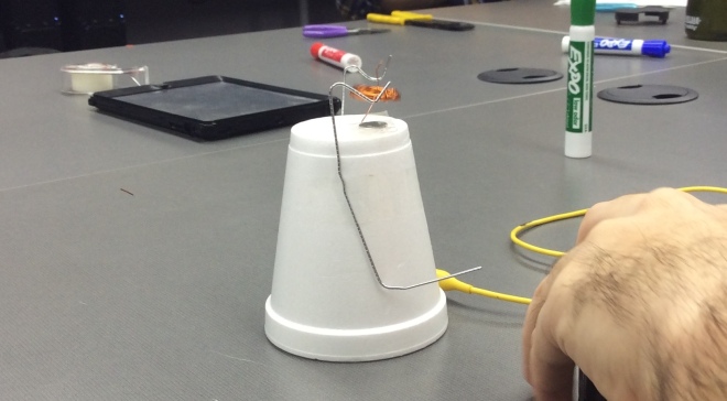
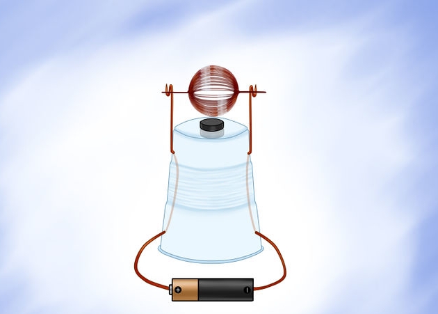
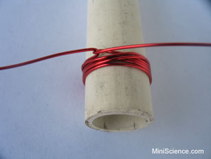
It is recommend that you wrap it around 15-20 times.  You will also need to leave about 2 inches on each side of the armature coil. When completed it should look similar to this.                                                                                                                                                                                                                                                                                            Loop_1
  2. Once you have completed in making the motor armature.  You will need to get a knife and begin scraping the insulation coating on the armature ends of the armature coil.                                                                                                                                                                                                                                                                                       Sanding_2                                                                                                                                                                          
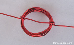
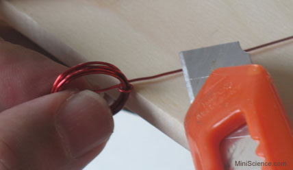
It is important to note that when you begin scraping the insulation coating. You need only scrape the top half of the wire.  Leaving the insulation on the the other side.  If done correctly one side will look really shiny.
  3.  Now that we have the motor armature completed.  We need next to make a perch.  This can be done by bending the paper clips to create a perch for the coil, so that the coil is held up with as little space as possible between the coil and the magnet.  This will have to be done with two paperclips.                                                                                                                                                                                                                                                                 download
  4.  Now that we have a motor armature and the perch that will hold it.  We need now to put it all together.  Take the paper clips and mount them on the Styrofoam cup.  This can be completed by using the tape to attach the paper clips to the cup.  Once secured go ahead and put the magnet on the base and secure with tape.  Then put the armature on the perch.  Once constructed it should look something like this.                                                 IMG_0714

Now that everything is in place its time to connect our copper wires to the paperclip leads. Take the copper wires, (2 different strands should suffice) and connect them to alligator clips.  The other end of the copper wires will be placed on the battery that you have.  One copper strand on the positive side of the battery and one copper strand on the negative side of the battery.  You can secure these leads with tape or hold it with you fingers for a stronger contact.  Now that you have completed this, all you have left to do is spin the armature gently to get the motor started. If done correctly it should look something like this.                                                                                                                                                                                                                                                                                                           728px-Build-a-Simple-Electric-Motor-Step-10

References:  

Conclusions: This lab experiment is an excellent demonstration of directional flow of electricity.  Essentially illustrating what is direct current.  Acquiring the lab materials required to complete this project is simple enough.  However if I were to attempt this a second time there would be some changes.  First thing I would do is reduce is the amount of times that I wrap the magnet wire.  It is recommended 15-20 times.  I say it would be better to cut that in half.  I wrapped my magnet wire about twenty times and it resulted in the armature being quite heavy.  This in turn makes it difficult to spin the armature to get the motor started and exponentially making it more difficult to balance.  Also I would emphasize taking my time with building the perch for the armature.  Paperclips are not the easiest materials to manipulate. Plus balancing on a styrofoam cup can be quite tedious.  Possibly using a different mounting surface that is capable of equipping a more durable perch.  It is also a solid recommendation to have an entirely different apparatus to hold the the copper wires in place on the battery.  This would ensure better contact and decrease resistance experienced in the flow of current.  Having said that, these materials and steps will get the job done.  But spending some extra time on acquiring more durable materials can make completion of this task far less troublesome.


CMST250 (Lab 1) Building a DC Motor